Installed on over 350 000 vehicles across the globe the child check mate system is the industry leading child reminder system.
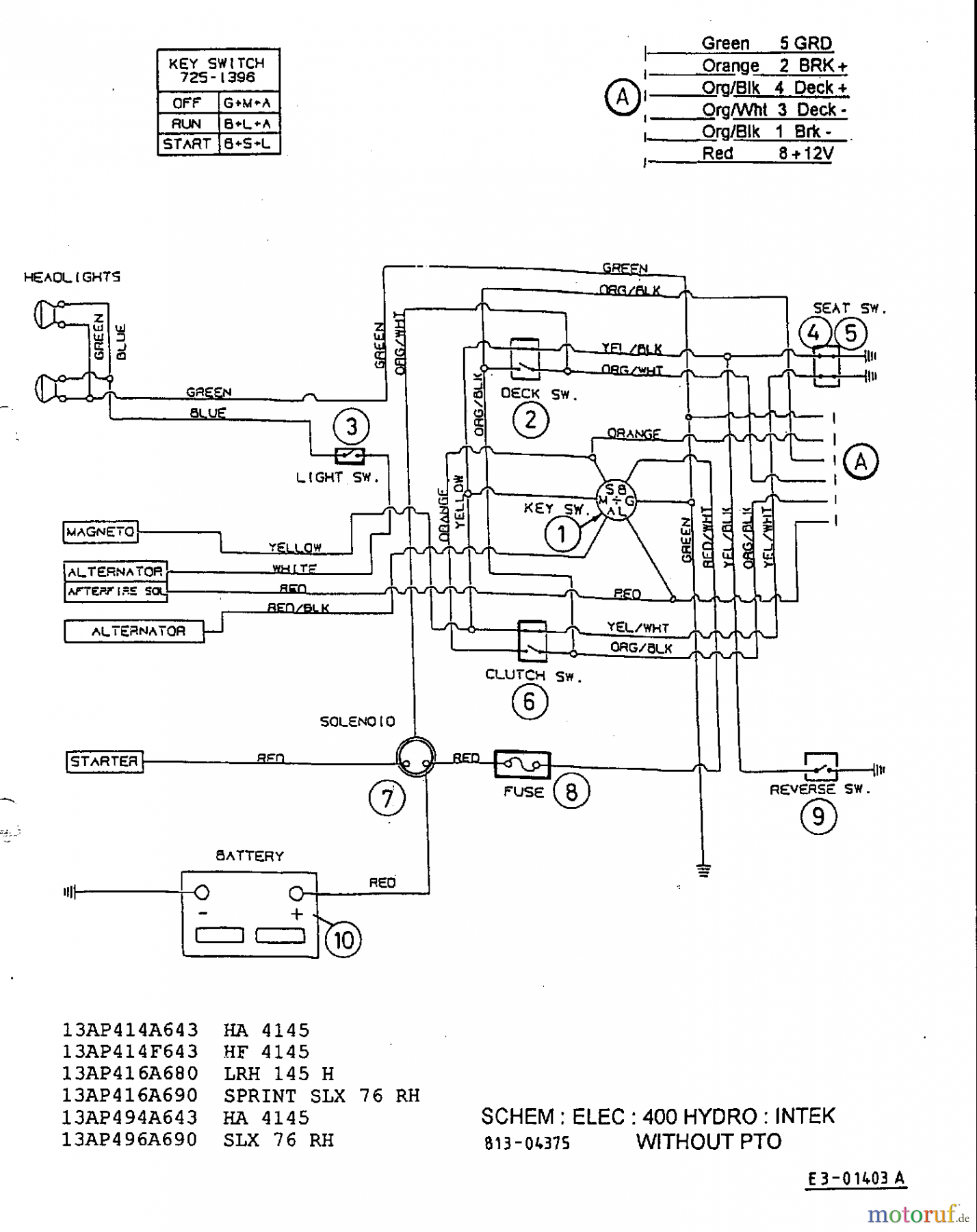
Child check mate system wiring diagram.
At this point the system is active and you may proceed with the regular operation of the vehicle.
Enjoy the videos and music you love upload original content and share it all with friends family and the world on youtube.
Wait 12 seconds and then trigger the activation wire.
Central states bus sales technical support team is happy to assist you in finding a wiring diagram for your bus or helping to diagnose your blue bird bus electrical system.
Activate the system by using the input where the brown wire 6 ph wire 5 is tied in.
Deactivating the child check mate system.
Wiring diagrams and a parts list can be found at the back of this manual.
The control module should be mounted behind the accessory panel so the driver does not have easy access to it.
Ease of installation our patented design allows for our system to use existing vehicle wiring reducing the need to run wires.
Child checkmate wiring diagram wiring diagram is a simplified tolerable pictorial representation of an electrical circuit it shows the components of the circuit as simplified shapes and the aptitude and signal friends with the devices.
The system will make quick beeping tones for 2 seconds.
The basic wiring diagram comes with the unit or can be found on at.
Make and verify all connections to the wiring harness before plugging in the control module.
Activate the system by using the input where the brown wire is tied in.
Activating the child check mate system turn the ignition on.
Child check mate system installation procedures.
Child check mate systems child check mate ep1plus.
The led should be mounted in a location that can easily be.
Installation videos of the ep1 and ep2 child check mate ccm systems including rear monitor and speaker.
There is a link on this webpage for blue bird wiring schematics by school bus body number.

